Architecture
Platforms
CE Platform
The Sipwise C5 CE platform is one single node running all necessary components of the system. The components are outlined in the following figure:

The main building blocks of Sipwise C5 are:
-
Provisioning
-
SIP Signaling and Media Relay
-
Mediation and Billing
SIP Signaling and Media Relay
In SIP-based communication networks, it is important to understand that the signaling path (e.g. for call setup and tear-down) is completely independent of the media path. On the signaling path, the involved endpoints negotiate the call routing (which user calls which endpoint, and via which path - e.g. using SIP peerings or going through the PSTN - the call is established) as well as the media attributes (via which IPs/ports are media streams sent and which capabilities do these streams have - e.g. video using H.261 or Fax using T.38 or plain voice using G.711). Once the negotiation on signaling level is done, the endpoints start to send their media streams via the negotiated paths.
The components involved in SIP and Media on the Sipwise C5 CE are shown in the following figure:

SIP Load-Balancer
The SIP load-balancer is a Kamailio instance acting as ingress and egress point for all SIP traffic to and from the system. It’s a high-performance SIP proxy instance based on Kamailio and is responsible for sanity checks of inbound SIP traffic. It filters broken SIP messages, rejects loops and relay attempts and detects denial-of-service and brute-force attacks and gracefully handles them to protect the underlying SIP elements. It also performs the conversion of TLS to internal UDP and vice versa for secure signaling between endpoints and Sipwise C5, and does far-end NAT traversal in order to enable signaling through NAT devices.
The load-balancer is the only SIP element in the system which exposes a SIP interface to the public network. Its second leg binds in the switch-internal network to pass traffic from the public internet to the corresponding internal components.
The name load-balancer comes from the fact that in the commercial version, when scaling out the system beyond one pair of servers, the load-balancer instance becomes its own physical node and then handles multiple pairs of proxies behind it.
On the public interface, the load-balancer listens on port 5060 for UDP and TCP, as well as on 5061 for TLS connections. On the internal interface, it speaks SIP via UDP on port 5060 to the other system components, and listens for XMLRPC connections on TCP port 5060, which can be used to control the daemon.
Its config files reside in /etc/ngcp-config/templates/etc/kamailio/lb/,
and changes to these files are applied by executing
ngcpcfg apply "my commit message".
The SIP load-balancer can be managed via the commands
ngcp-service start kamailio-lb, ngcp-service stop kamailio-lb and
ngcp-service restart kamailio-lb. Its status can be queried by executing
ngcp-service status kamailio-lb or ngcp-service summary | grep "kamailio-lb".
Also ngcp-kamctl lb and ngcp-kamcmd lb are provided for querying
kamailio functions, for example: ngcp-kamcmd lb htable.dump ipban.
Execute the command: ngcp-kamctl lb fifo system.listMethods or
ngcp-kamcmd lb system.listMethods to get the list of all available
queries.
|
SIP Proxy/Registrar
The SIP proxy/registrar (or short proxy) is the work-horse of Sipwise C5. It’s also a separate Kamailio instance running in the switch-internal network and is connected to the provisioning database via MySQL, authenticates the endpoints, handles their registrations on the system and does the call routing based on the provisioning data. It is also connected to no-sql backend (Redis) for processing speed purposes and for e.g. in this way manages ACC data, location records etc. For each call, the proxy looks up the provisioned features of both the calling and the called party (either subscriber or domain features if it’s a local caller and/or callee, or peering features if it’s from/to an external endpoint) and acts accordingly, e.g. by checking if the call is blocked, by placing call-forwards if applicable and by normalizing numbers into the appropriate format, depending on the source and destination of a call.
It also writes start- and stop-records for each call, which are then transformed into call detail records (CDR) by the mediation system.
If the endpoints indicate negotiation of one or more media streams, the proxy also interacts with the Media Relay to open, change and close port pairs for relaying media streams over Sipwise C5, which is especially important to traverse NAT.
The proxy listens on UDP port 5062 in the system-internal network. It cannot be reached directly from the outside, but only via the SIP load-balancer.
Its config files reside in /etc/ngcp-config/templates/etc/kamailio/proxy/, and changes to these files are applied by executing ngcpcfg apply "my commit message".
The SIP proxy can be controlled via the commands
ngcp-service start kamailio-proxy, ngcp-service stop kamailio-proxy and
ngcp-service restart kamailio-proxy. Its status can be queried by executing
ngcp-service status kamailio-proxy or ngcp-service summary | grep "kamailio-proxy".
Also ngcp-kamctl proxy and ngcp-kamcmd proxy are provided for querying
kamailio functions, for example: ngcp-kamctl proxy ul show.
Execute the command: ngcp-kamctl proxy fifo system.listMethods or
ngcp-kamcmd proxy system.listMethods to get the list of all available
queries.
|
SIP Back-to-Back User-Agent (B2BUA)
The SIP B2BUA (also called SBC within the system) decouples the first call-leg (calling party to Sipwise C5) from the second call-leg (Sipwise C5 to the called party).
The software part used for this element is SEMS.
This element is typically optional in SIP systems, but it is always used for SIP calls (INVITE) that don’t have Sipwise C5 as endpoint. It acts as application server for various scenarios (e.g. for feature provisioning via Vertical Service Codes and as Conferencing Server) and performs the B2BUA decoupling, topology hiding, caller information hiding, SIP header and Media feature filtering, outbound registration, outbound authentication and call length limitation as well as Session Keep-Alive handler.
Due to the fact that typical SIP proxies (like the load-balancer and proxy in Sipwise C5) do only interfere with the content of SIP messages where it’s necessary for the SIP routing, but otherwise leave the message intact as received from the endpoints, whereas the B2BUA creates a new call leg with a new SIP message from scratch towards the called party, SIP message sizes are reduced significantly by the B2BUA. This helps to bring the message size under 1500 bytes (which is a typical default value for the MTU size) when it leaves Sipwise C5. That way, chances of packet fragmentation are quite low, which reduces the risk of running into issues with low-cost SOHO routers at customer sides, which typically have problems with UDP packet fragmentation.
The SIP B2BUA only binds to the system-internal network and listens on UDP port 5080 for SIP messages from the load-balancer or the proxy, on UDP port 5048 for control messages from the cli tool and on TCP port 8090 for XMLRPC connections to control the daemon.
In cases when B2B is engaged into processing the media (RTP/RTCP data), it uses this UDP ports range by default: 15000 - 19999.
Its configuration files reside in /etc/ngcp-config/templates/etc/ngcp-sems, and changes to these files are applied by executing ngcpcfg apply "my commit message".
The SIP B2BUA can be controlled via the commands
ngcp-service start sems, ngcp-service stop sems and
ngcp-service restart sems. Its status can be queried by executing
ngcp-service status sems or ngcp-service summary | grep "sems".
|
SIP App-Server
The SIP App-Server is an Asterisk instance used for voice applications like Voicemail and Reminder Calls. Asterisk uses the MySQL database as a message spool for voicemail, so it doesn’t directly access the file system for user data. The voicemail plugin is a slightly patched version based on Asterisk 16.2.1 to make Asterisk aware of Sipwise C5 internal UUIDs for each subscriber. That way a SIP subscriber can have multiple E164 phone numbers, but all of them terminate in the same voicebox.
The App-Server listens on the internal interface on UDP port 5070 for SIP messages and by default uses media ports in the range from UDP port 10000 to 14999.
The configuration files reside in /etc/ngcp-config/templates/etc/asterisk, and changes to these files are applied by executing ngcpcfg apply "my commit message".
The SIP App-Server can be controlled via the commands
ngcp-service start asterisk, ngcp-service stop asterisk and
ngcp-service restart asterisk. Its status can be queried by executing
ngcp-service status asterisk or ngcp-service summary | grep "asterisk".
|
Message Routing and Media Relay
The Media Relay (also called rtpengine) is a Kernel-based packet relay, which is controlled by the SIP proxy. For each media stream (e.g. a voice and/or video stream), it maintains a pair of ports in the range of port number 30000 to 44999. When the media streams are negotiated, rtpengine opens the ports in user-space and starts relaying the packets to the addresses announced by the endpoints. If packets arrive from different source addresses than announced in the SDP body of the SIP message (e.g. in case of NAT), the source address is implicitly changed to the address the packets are received from. Once the call is established and the rtpengine has received media packets from both endpoints for this call, the media stream is pushed into the kernel and is then handled by a custom Sipwise iptables module to increase the throughput of the system and to reduce the latency of media packets.
The rtpengine internally listens on UDP port 12222 for control messages from the SIP proxy. For each media stream, it opens two pairs of UDP ports on the public interface in the range of 30000 and 40000 per default, one pair on even port numbers for the media data, and one pair on the next odd port numbers for metadata, e.g. RTCP in case of RTP streams. Each endpoint communicates with one dedicated port per media stream (opposed to some implementations which use one pair for both endpoints) to avoid issues in determining where to send a packet to. The rtpengine also sets the QoS/ToS/DSCP field of each IP packet it sends to a configured value, 184 (0xB8, expedited forwarding) by default.
The kernel-internal part of the rtpengine is facilitated through an
iptables module having the target name RTPENGINE. If any
additional firewall or packet filtering rules are installed, it is
imperative that this rule remains untouched and stays in place. Otherwise,
if the rule is removed from iptables, the kernel will not be able to
forward the media packets and forwarding will fall back to the user-space
daemon. The packets will still be forwarded normally, but performance
will be much worse under those circumstances, which will be especially
noticeable when a lot of media streams are active concurrently. See the
section on Firewalling
for more information.
The rtpengine configuration file is
/etc/ngcp-config/templates/etc/default/ngcp-rtpengine-daemon, and
changes to this file are applied by executing
ngcpcfg apply "my commit message". The UDP port range can be
configured via the config.yml file under the section rtpengine.
The QoS/ToS value can be changed via the key qos.tos_rtp.
The Media Relay can be controlled via the commands
ngcp-service start rtpengine, ngcp-service stop rtpengine and
ngcp-serivce restart rtpengine. Its status can be queried by executing
ngcp-service status rtpengine" or ngcp-service summary | grep "rtpengine".
|
Redis Database
The Redis database is used as a high-perfomance key/value storage for global system data. This includes calls information and concurrent calls counters for customers and subscribers, etc..
Scaling CARRIER beyond one Hardware Chassis
If Sipwise C5 CARRIER is scaled beyond 250,000 subscribers and therefore exceeds one chassis, a second chassis is put into place. This chassis provides another two web servers, two db servers, two load balancers and 8 proxies, doubling the capacity of the system.
Scaling the DB cluster
The DB cluster is the only node type which requires a notable change on the architecture.
DB01a/b nodes have master<->master replication for High-Availability
DB01→prx01a + DB01→prx01b are master→slave replication for read/write scale (write to remote/shared db01, read from local prx DB).
Separate hot and cold data. Hot in Redis for low IO. Cold in MariaDB.
Separate huge data (e.g. voicemail, voisniff data) to separate 'storage' DB node.
With such setup the central db01 pair can handle all the planned and unexpected DB load without the significant hardware resource usage. DB01a and DB01b can be located in different Geo-locations for High-Availability (low latency link is required for replications).
Further DB nodes scalability can be achieved using Geo-redundant setup. Please contact Sipwise sales team for more details here.
Scaling the proxy cluster
New proxy nodes replicate via master/slave from the db nodes in the chassis as usual. Since the db cluster holds all provisioning information of all subscribers, the proxy nodes join the cluster transparently and will start serving subscribers as soon as all services on a new proxy are reachable from the load balancers.
Scaling the load balancers
Load balancers start serving subscribers as soon as they are made visible to the subscribers. This could either be done via DNS round-robin, but the better approach is to configure a DNS SRV record, which allows for more fine-grained control like weighting load-balancer pairs and allowing fail-over from one pair to another on the client side.
The load balancers use the Path extension of SIP to make sure during SIP registration that calls targeted to a subscriber are routed via the same load balancer pair which the subscriber used during registration for proper traversal of symmetric NAT at the customer premise.
A SIP or XMPP request reaching a load balancer can be routed to any available proxy in the whole system, or only to proxies belonging to the same chassis as the load balancer, depending on the system configuration.
Scaling to a Geo-Redundant setup
A basic Geo-Redundant configuration can be achieved by simply deploying all the sp1 nodes (A nodes in case of CARRIER) into a location and the sp2 nodes (B nodes in case of CARRIER) into another one. The locations have to be connected by a reliable and low latency layer 2 link.
This setup has many advantages and gives the possibility to have full business continuity in case one of the locations goes completely down but it has also some drawbacks:
-
in case one site goes down, the remaining site is in an 'unstable' state due to missing HA nodes.
-
only one location is active at a time. Therefore it is not possibile to take advantage of all the benefits of a geo-located system. This can be improved by activating services as 'instances' as described here.
-
in case the connection between the two systems goes down, a split brain scenario will happen causing an instability of the whole system.
A new alternative approach consists of the deployment of two fully operational PRO or Carrier systems, from now on referred to as 'cluster', connected by the aforementioned reliable and low latency layer 2 link.
Compared to the previous setup, this configuration has the following advantages:
-
single management interface access (API and Web interface) for both systems
-
geo-locate the SIP/RTP connections and traffic in order to always connect endpoints to the nearest cluster (it requires dedicated network configurations)
-
fallback of the endpoint connections to the other cluster node
-
communications between subscribers registered on different clusters remains internal
-
in case one cluster goes down, the other continues to work in standard mode with a local HA
-
in case the interconnection between clusters down, the two systems continue to work independently. After the connection is re-established, a dedicated DB resynchronization will happen.
IMPORTATNT: In this architecture the interconnection link between the two clusters will be used not only for database replica and internal synchronization but also for internal SIP/RTP traffic. Due to that, it is important that the link has very low latency and high throughput.
The final setup looks like:
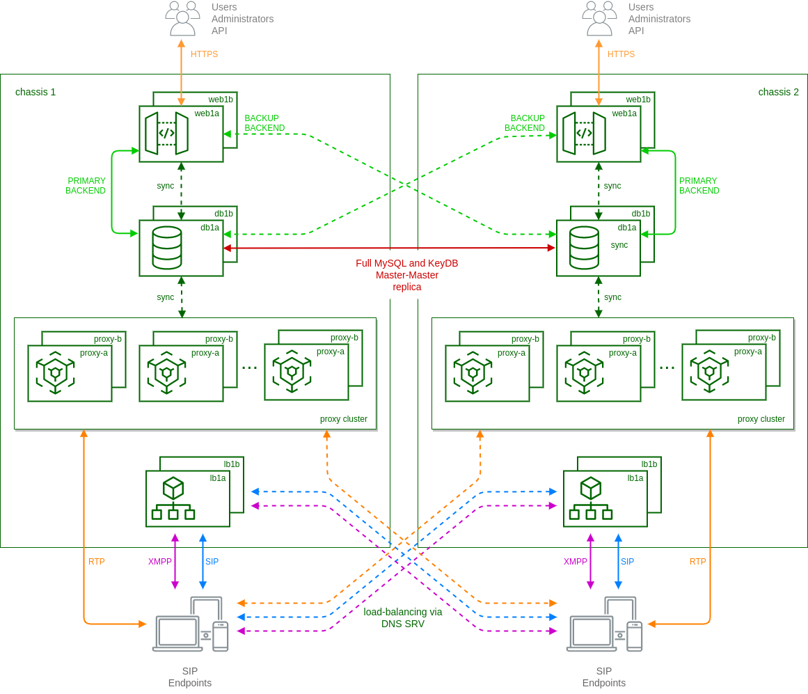
In particular:
-
each 'web' node has a built-in mechanism based on ha-proxy to select which 'db' node to use as backend. By default they always try to use the local node as primary connection and switch to the remote node in case of missing local connection or faulty local replica status.
-
mysql and keydb databases running on 'db' nodes are in a full master-master replica setup. This is to ensure the presence of same data (provisioning, locations, CDRs, etc.) on both clusters.
-
each cluster uses local 'lb' and 'prx' nodes as in standard carrier architecture, except when the called subscriber is registered on the other cluster. In these cases local 'prx' node can directly contact the remote 'lb' to route the calls to the final destination.
-
using DNS-SRV records, endpoints are usually registered on the nearest cluster. In case of failure of the local connection, then DNS-SRV is responsible to route new registrations to remote cluster.
-
ngcpcfg framework enables the operator to manage the whole system from one cluster node.
For any additional details on the Geo-Redundant setup and how to configure it, please contact Sipwise sales.