Architecture
Platforms
CARRIER Platform
The Sipwise C5 CARRIER platform is composed by a cluster of four different node types, which are all deployed in active/standby pairs:
-
Web-Servers (web1a/web1b): Provide northbound interfaces (CSC, API) via HTTPS for provisioning
-
DB-Servers (db1a/db1b): Provide the central persistent SQL data store for customer data, peering configuration, billing data etc.
-
Proxy-Servers (proxy1a/proxy1b .. proxy4a/proxy4b): Provide the SIP and XMPP signalling engines, application servers and media relays to route Calls and IM/Presence and serve media to the endpoints.
-
Load-Balancers (lb1a/lb1b): Provide a perimeter for SIP and XMPP signalling.

The system is provisioned via the web servers on a central pair of db servers. Signalling is entering the system via the lb servers to a cluster of proxies, which in turn communicate directly (caching and shared data) and indirectly (static provisioning data replicated via master/slave) with the db servers. Each pair of proxy is capable of handling any subscriber, so subscribers are not bound to specific "home proxies". Once a call starts on a proxy pair, it is ensured that the full range of services is provided on that pair (voicemail, media, billing, …) until call-teardown. Failures on an active proxy node cause a fail-over to the corresponding stand-by node within the proxy pair, taking over the full signalling and media without interruptions.
PRO Platform
The Sipwise C5 PRO platform consists of two identical appliances working in active/standby mode. The components of a node are outlined in the following figure:

The main building blocks of Sipwise C5 are:
-
Provisioning
-
SIP Signaling and Media Relay
-
Mediation and Billing
-
Monitoring and Alerting
-
High Availability and Fail-Over
Provisioning
Any HTTPS traffic for provisioning (web interfaces, northbound APIs) but also for phone auto-provisioning enters the platform on the active web server. The web server runs an nginx instance acting as a reverse proxy for the ngcp-panel process, which in turn provides the provisioning functionality.
The web server is connected to the db server pair, which provides a persistent relational data store via MySQL and a high-performance system cache using Redis key-value store.
API and Web Interface

The web server pair is an active/standby pair of nodes connected via an HA service (GCS/CRM). If one of the servers fail (by losing connection to the outside while the standby server is still connected, or caused by a hardware failure, or if it’s down due to maintenance), the standby server takes over the shared IP address of the active node and continues serving the provisioning interface.
SIP Signaling and Media Relay
In SIP-based communication networks, it is important to understand that the signaling path (e.g. for call setup and tear-down) is completely independent of the media path. On the signaling path, the involved endpoints negotiate the call routing (which user calls which endpoint, and via which path - e.g. using SIP peerings or going through the PSTN - the call is established) as well as the media attributes (via which IPs/ports are media streams sent and which capabilities do these streams have - e.g. video using H.261 or Fax using T.38 or plain voice using G.711). Once the negotiation on signaling level is done, the endpoints start to send their media streams via the negotiated paths.
On a CARRIER any signalling traffic enters and leaves the system via load balancers, which act as a perimeter towards the customer devices and performs NAT handling, DoS and DDoS mitigation. New connections are routed to a random pair of proxy servers, which do the actual routing for SIP and XMPP. The proxy servers also engage media relays for voice and video streams, which bypass the load balancers and communicate directly with the customer devices for performance reasons.
The components involved in SIP and Media on the Sipwise C5 PRO/CARRIER are shown in the following figure:

SIP Load-Balancer
The SIP load-balancer is a Kamailio instance acting as ingress and egress point for all SIP traffic to and from the system. It’s a high-performance SIP proxy instance based on Kamailio and is responsible for sanity checks of inbound SIP traffic. It filters broken SIP messages, rejects loops and relay attempts and detects denial-of-service and brute-force attacks and gracefully handles them to protect the underlying SIP elements. It also performs the conversion of TLS to internal UDP and vice versa for secure signaling between endpoints and Sipwise C5, and does far-end NAT traversal in order to enable signaling through NAT devices.
The load-balancer is the only SIP element in the system which exposes a SIP interface to the public network. Its second leg binds in the switch-internal network to pass traffic from the public internet to the corresponding internal components.
The name load-balancer comes from the fact that when scaling out Sipwise C5 beyond one pair of servers, the load-balancer instance becomes its own physical node and then handles multiple pairs of proxies behind it.
On the public interface, the load-balancer listens on port 5060 for UDP and TCP, as well as on 5061 for TLS connections. On the internal interface, it speaks SIP via UDP on port 5060 to the other system components, and listens for XMLRPC connections on TCP port 5060, which can be used to control the daemon.

A node in a load balancer pair runs two services besides the usual HA service.
One is a state-less instance of kamailio, providing an extremely fast relay of SIP messages. Kamailio takes care of converting TCP and TLS connections from the customer devices to UDP for internal communication towards proxies, and it performs far-end NAT traversal by inspecting the SIP messages and comparing it to the actual source address where packets have been received from, then modifying the SIP messages accordingly. If a SIP message is received by the load balancer, it distinguishes between new and ongoing SIP transactions by inspecting the To-Tags of a message, and it determines whether the message is part of an established dialog by inspecting the Route header. Sanity checks are performed on the headers to make sure the call flows adhere to certain rules for not being able to bypass any required element in the routing path. In-dialog messages are routed to the corresponding proxy servers according to the Route defined in the message. Messages initiating a new transaction and/or dialog (registrations, calls etc) are routed to a randomly selected proxy. The selection algorithm is based on a hash over the Call-ID of the message, so the same proxy sending a authentication challenge to an endpoint will receive the authenticated message again.
The second service running on a load balancer is haproxy, which is acting as load balancing instance for XMPP messages. The same way the SIP load balancer routes SIP messages to the corresponding proxy, the haproxy passes XMPP traffic on to the proxy maintaining a session with a subscriber, or randomly selects a proxy in case of a new connection while automatically failing over on timeouts.
Its config files reside in /etc/ngcp-config/templates/etc/kamailio/lb/,
and changes to these files are applied by executing
ngcpcfg apply "my commit message".
The SIP load-balancer can be managed via the commands
ngcp-service start kamailio-lb, ngcp-service stop kamailio-lb and
ngcp-service restart kamailio-lb. Its status can be queried by executing
ngcp-service status kamailio-lb or ngcp-service summary | grep "kamailio-lb".
Also ngcp-kamctl lb and ngcp-kamcmd lb are provided for querying
kamailio functions, for example: ngcp-kamcmd lb htable.dump ipban.
Execute the command: ngcp-kamctl lb fifo system.listMethods or
ngcp-kamcmd lb system.listMethods to get the list of all available
queries.
|
SIP Proxy/Registrar
The SIP proxy/registrar (or short proxy) is the work-horse of Sipwise C5. It’s also a separate Kamailio instance running in the switch-internal network and is connected to the provisioning database via MySQL, authenticates the endpoints, handles their registrations on the system and does the call routing based on the provisioning data. It is also connected to no-sql backend (Redis) for processing speed purposes and for e.g. in this way manages ACC data, location records etc. For each call, the proxy looks up the provisioned features of both the calling and the called party (either subscriber or domain features if it’s a local caller and/or callee, or peering features if it’s from/to an external endpoint) and acts accordingly, e.g. by checking if the call is blocked, by placing call-forwards if applicable and by normalizing numbers into the appropriate format, depending on the source and destination of a call.
It also writes start- and stop-records for each call, which are then transformed into call detail records (CDR) by the mediation system.
If the endpoints indicate negotiation of one or more media streams, the proxy also interacts with the Media Relay to open, change and close port pairs for relaying media streams over Sipwise C5, which is especially important to traverse NAT.
The proxy listens on UDP port 5062 in the system-internal network. It cannot be reached directly from the outside, but only via the SIP load-balancer.
Its config files reside in /etc/ngcp-config/templates/etc/kamailio/proxy/, and changes to these files are applied by executing ngcpcfg apply "my commit message".
The SIP proxy can be controlled via the commands
ngcp-service start kamailio-proxy, ngcp-service stop kamailio-proxy and
ngcp-service restart kamailio-proxy. Its status can be queried by executing
ngcp-service status kamailio-proxy or ngcp-service summary | grep "kamailio-proxy".
Also ngcp-kamctl proxy and ngcp-kamcmd proxy are provided for querying
kamailio functions, for example: ngcp-kamctl proxy ul show.
Execute the command: ngcp-kamctl proxy fifo system.listMethods or
ngcp-kamcmd proxy system.listMethods to get the list of all available
queries.
|
SIP Back-to-Back User-Agent (B2BUA)
The SIP B2BUA (also called SBC within the system) decouples the first call-leg (calling party to Sipwise C5) from the second call-leg (Sipwise C5 to the called party).
The software part used for this element is a commercial version of SEMS, with the main difference to the open-source version that it includes a replication module to share its call states with the stand-by node.
This element is typically optional in SIP systems, but it is always used for SIP calls (INVITE) that don’t have Sipwise C5 as endpoint. It acts as application server for various scenarios (e.g. for feature provisioning via Vertical Service Codes and as Conferencing Server) and performs the B2BUA decoupling, topology hiding, caller information hiding, SIP header and Media feature filtering, outbound registration, outbound authentication, Prepaid accounting and call length limitation as well as Session Keep-Alive handler.
Due to the fact that typical SIP proxies (like the load-balancer and proxy in Sipwise C5) do only interfere with the content of SIP messages where it’s necessary for the SIP routing, but otherwise leave the message intact as received from the endpoints, whereas the B2BUA creates a new call leg with a new SIP message from scratch towards the called party, SIP message sizes are reduced significantly by the B2BUA. This helps to bring the message size under 1500 bytes (which is a typical default value for the MTU size) when it leaves Sipwise C5. That way, chances of packet fragmentation are quite low, which reduces the risk of running into issues with low-cost SOHO routers at customer sides, which typically have problems with UDP packet fragmentation.
The SIP B2BUA only binds to the system-internal network and listens on UDP port 5080 for SIP messages from the load-balancer or the proxy, on UDP port 5048 for control messages from the cli tool and on TCP port 8090 for XMLRPC connections to control the daemon.
In cases when B2B is engaged into processing the media (RTP/RTCP data), it uses this UDP ports range by default: 15000 - 19999.
Its configuration files reside in /etc/ngcp-config/templates/etc/sems-b2b, and changes to these files are applied by executing ngcpcfg apply "my commit message".
The SIP B2BUA can be controlled via the commands
ngcp-service start b2b, ngcp-service stop b2b and
ngcp-service restart b2b. Its status can be queried by executing
ngcp-service status b2b or ngcp-service summary | grep "b2b".
|
SIP App-Server
The SIP App-Server is an Asterisk instance used for voice applications like Voicemail and Reminder Calls. It is also used in the software-based Faxserver solution to transcode SIP and RTP into the IAX protocol and vice versa, in order to talk to the Software Fax Modems. Asterisk uses the MySQL database as a message spool for voicemail, so it doesn’t directly access the file system for user data. The voicemail plugin is a slightly patched version based on Asterisk 16.2.1 to make Asterisk aware of Sipwise C5 internal UUIDs for each subscriber. That way a SIP subscriber can have multiple E164 phone numbers, but all of them terminate in the same voicebox.
The App-Server listens on the internal interface on UDP port 5070 for SIP messages and by default uses media ports in the range from UDP port 10000 to 14999.
The configuration files reside in /etc/ngcp-config/templates/etc/asterisk, and changes to these files are applied by executing ngcpcfg apply "my commit message".
The SIP App-Server can be controlled via the commands
ngcp-service start asterisk, ngcp-service stop asterisk and
ngcp-service restart asterisk. Its status can be queried by executing
ngcp-service status asterisk or ngcp-service summary | grep "asterisk".
|
Message Routing and Media Relay
The Media Relay (also called rtpengine) is a Kernel-based packet relay, which is controlled by the SIP proxy. For each media stream (e.g. a voice and/or video stream), it maintains a pair of ports in the range of port number 30000 to 44999. When the media streams are negotiated, rtpengine opens the ports in user-space and starts relaying the packets to the addresses announced by the endpoints. If packets arrive from different source addresses than announced in the SDP body of the SIP message (e.g. in case of NAT), the source address is implicitly changed to the address the packets are received from. Once the call is established and the rtpengine has received media packets from both endpoints for this call, the media stream is pushed into the kernel and is then handled by a custom Sipwise iptables module to increase the throughput of the system and to reduce the latency of media packets.
The rtpengine internally listens on UDP port 12222 for control messages from the SIP proxy. For each media stream, it opens two pairs of UDP ports on the public interface in the range of 30000 and 40000 per default, one pair on even port numbers for the media data, and one pair on the next odd port numbers for metadata, e.g. RTCP in case of RTP streams. Each endpoint communicates with one dedicated port per media stream (opposed to some implementations which use one pair for both endpoints) to avoid issues in determining where to send a packet to. The rtpengine also sets the QoS/ToS/DSCP field of each IP packet it sends to a configured value, 184 (0xB8, expedited forwarding) by default.
The kernel-internal part of the rtpengine is facilitated through an
iptables module having the target name RTPENGINE. If any
additional firewall or packet filtering rules are installed, it is
imperative that this rule remains untouched and stays in place. Otherwise,
if the rule is removed from iptables, the kernel will not be able to
forward the media packets and forwarding will fall back to the user-space
daemon. The packets will still be forwarded normally, but performance
will be much worse under those circumstances, which will be especially
noticeable when a lot of media streams are active concurrently. See the
section on Firewalling
for more information.

Proxy servers also come in pairs, and by default there are four pairs of proxies in a standard Sipwise C5 CARRIER setup.
The proxies are responsible for doing the actual SIP routing and media handling and the XMPP presence and chat message deliveries. Each proxy pair can handle any subscriber on the overall system, compared to the concept of "home proxies" in other architectures. The advantage of this approach is that the overall system can be scaled extremely easily by adding more proxy pairs without having to redistribute subscribers.
Once a load balancer sends a new message to a proxy, the SIP transaction and/or dialog gets anchored to this proxy. That way it is ensured that a call starting on a proxy is also ended on the same proxy. Hence, the full range of feature handling like media relay, voicemail, fax, billing and rating is performed on this proxy. So, there is no a central point for various tasks, potentially leading to a non-scalable bottleneck. Due to the anchoring, proxies come in pairs and replicate all internal state information to the standby node via Redis. In case of fail-over, the full signalling and media are moved to the standby node without interruption.
The complete static subscriber information like authentication credentials, number mappings, feature settings etc. are replicated from the db cluster down to the local MySQL instance of the proxies. The ratio of db read requests of static subscriber data versus reading and writing volatile and shared data is around 15:1, and this approach moves the majority of the static read operations from the central db cluster to the local proxy db.
Volatile and shared information needed by all proxies in the cluster is read from and written to the db cluster. This mainly includes SIP registration information and XMPP connection information.
Billing and rating is also performed locally on the proxies, and only completed CDRs (rated or unrated depending on whether rating is enabled) are transferred to the central db cluster for consumption via the northbound interfaces.
For SIP, the relevant instances on a proxy are kamailio acting as a stateful proxy for SIP registration and call routing, sems acting as a back-to-back user-agent for prepaid billing and application server, rtpengine as media relay and RTP/SRTP transcoder, and asterisk as voicemail server. XMPP is handled by an instance of prosody, and several billing processes mediate start and stop records into CDRs and rate them according to the relevant billing profiles.
The rtpengine configuration file is
/etc/ngcp-config/templates/etc/default/ngcp-rtpengine-daemon, and
changes to this file are applied by executing
ngcpcfg apply "my commit message". The UDP port range can be
configured via the config.yml file under the section rtpengine.
The QoS/ToS value can be changed via the key qos.tos_rtp.
The Media Relay can be controlled via the commands
ngcp-service start rtpengine, ngcp-service stop rtpengine and
ngcp-serivce restart rtpengine. Its status can be queried by executing
ngcp-service status rtpengine" or ngcp-service summary | grep "rtpengine".
|
MySQL Database
The MySQL database consists of a pair of active/standby MySQL servers. They run a MySQL master/master replication with replication integrity checks to ensure data consistency and redundancy.
The MySQL servers on both physical nodes synchronize via the row-based master/master replication. In theory, any of the two servers in the pair can be used to write data to the database, however, in practice the shared IP address is used towards clients accessing the service, hence only the active MySQL server will receive the write requests and replicate them to the standby one.
Provisioning Database (CARRIER-only)

The db server pair is another active/standby pair with automatic fail-over. Nodes in the pair are running a MySQL master/master replication with replication integrity checks to ensure data redundancy and safety. Any changes via provisioning interfaces are stored in the MySQL cluster. The second service is a Redis master/slave replication with automatic master propagation on fail-over. This Redis cluster is used as a high-performance volatile system cache for various components which need to share state information across nodes.
Persistent MySQL Database (CARRIER-only)
The MySQL instances on the db nodes synchronize via row-based master/master replication. In theory, any of the two servers in the pair can be used to write data to the database, however in practice a shared IP is used towards clients accessing the service, so only one node will receive the write requests. This is done to ensure transparent and instant convergence of the db cluster on fail-over for the clients.
On top of that, the first node of the db pair also acts as a master in a master/slave replication towards all proxy nodes in the system. That way, proxies can access read-only provisioning data directly from their local databases, resulting in reduced latency and significant off-loading of read queries on the central db cluster.
Redis Database
The Redis database is used as a high-perfomance key/value storage for global system datashared across proxies. This includes calls information and concurrent calls counters for customers and subscribers, etc..
The active-standby replication ensures that the data is immediately copied from the active node to the standby one. As all sensitive call information is held in the shared storage, Sipwise C5 makes it possible to switch the operational state from active to standby on one physical node and from standby to active on the other node without any call interruptions. Your subscribers will never notice that their calls being established on one physical server, were successfully moved to another one and successfully completed there.
On a CARRIER a Redis master/slave setup is used to provide a high-perfomance key/value storage for global system data shared across proxies. This includes concurrent call counters for customers and subscribers, as a subscriber could place two simultaneous calls via two different proxy pairs.
High Availability and Fail-Over
Overview
The two servers of a complete Sipwise C5 system form a pair, a simple
cluster with two nodes. Their names are fixed as sp1 and sp2, however
neither of them is inherently a first or a second. They’re both equal
and identical and either can be the active node of the cluster at any time.
Only one node is always ever active, the other one is in standby mode and
does not perform any active functions.
High availability is achieved through constant communication between the two nodes and constant state replication from the active node to the standby one. Whenever the standby node detects that the other node has become unresponsive, has gone offline and has failed in any other way, it will proceed with taking over all resources and becoming the active node, with all operations resuming where the failed node has left off. Through that, the system will remain fully operational and service disruption will be minimal.
When the failed node comes back to life, it will become the new standby node, replicate everything that has changed in the meantime from the new active node, and then the cluster will be back in fully highly available state.
| The login banner at the SSH shell provides information about whether the local system is currently the active one or the standby one. See Administration for other ways to differentiate between the active and the standby node. |
Nomenclature and Alternatives
The HA architecture consists of two components: the Group Communication System, also known as GCS, and the Cluster Resource Manager, also known as CRM. Sipwise C5 supports two alternatives for these components:
-
Corosync/Pacemaker: This is the newer and more modern software and the successor of Heartbeat version 2. It splits the HA framework into its two components, with Corosync providing the GCS service and Pacemaker providing the CRM service. It provides several additional features over Heartbeat version 2, and is the default for new Sipwise C5 installations. See the Corosync/Pacemaker chapter for detailed information.
-
Heartbeat version 2: This is the older and more basic software which provided both GCS and CRM services. It is now obsolete and not available anymore, and systems that use it should have been migrated away before upgrading to this release.
Core Concepts and Configuration
The direct Ethernet crosslink between the two nodes provides the main mechanism of HA communication between them. All state replication happens over this link. Additionally, the GCS service uses this link to communicate with the other node to see if it’s still alive and active. A break in this link will therefore result in a split brain scenario, with either node trying to become the active one. This is to be avoided at all costs.
The config.yml file allows specification of a list of ping nodes under
the key ha.pingnodes, which are used by the CRM service to determine
if local network communications are healthy. Both servers will then constantly
compare the number of locally reachable ping nodes with each other, and if the
standby server is able to reach more of them, then it will become the active
one.
The main resource that the CRM service manages is the shared service IP address.
Each node has its own static IP address configured on its first Ethernet
interface (neth0), which is done outside of the Sipwise C5 configuration
framework (i.e. in the Debian-specific config file /etc/network/interfaces).
The shared service IP is specified in network.yml at the key
hosts.sp1|sp2.neth0.shared_ip. The CRM service will configure it as a
secondary IP address on the first Ethernet interface (neth0:0) on the active
node and will deconfigure it on the standby node. Thus, all network
communications with this IP address will always go only to the currently active
node.
Administration
The current status of the local Sipwise C5 node can be determined using
the ngcp-check-active shell command. This command produces no output,
but returns an exit status of 0 for the active node and 1 for the
standby node. A more complete shell command to produce visible output could
be: ngcp-check-active -v
To force a currently active node into standby mode, use the command
ngcp-make-standby. For the opposite effect, use the command
ngcp-make-active. This will also always affect the state of the other
node, as the system automatically makes sure that always only one node is
active at a time.
Scaling CARRIER beyond one Hardware Chassis
If Sipwise C5 CARRIER is scaled beyond 250,000 subscribers and therefore exceeds one chassis, a second chassis is put into place. This chassis provides another two web servers, two db servers, two load balancers and 8 proxies, doubling the capacity of the system.
Scaling the DB cluster
The DB cluster is the only node type which requires a notable change on the architecture.
DB01a/b nodes have master<->master replication for High-Availability
DB01→prx01a + DB01→prx01b are master→slave replication for read/write scale (write to remote/shared db01, read from local prx DB).
Separate hot and cold data. Hot in Redis for low IO. Cold in MariaDB.
Separate huge data (e.g. voicemail, voisniff data) to separate 'storage' DB node.
With such setup the central db01 pair can handle all the planned and unexpected DB load without the significant hardware resource usage. DB01a and DB01b can be located in different Geo-locations for High-Availability (low latency link is required for replications).
Further DB nodes scalability can be achieved using Geo-redundant setup. Please contact Sipwise sales team for more details here.
Scaling the proxy cluster
New proxy nodes replicate via master/slave from the db nodes in the chassis as usual. Since the db cluster holds all provisioning information of all subscribers, the proxy nodes join the cluster transparently and will start serving subscribers as soon as all services on a new proxy are reachable from the load balancers.
Scaling the load balancers
Load balancers start serving subscribers as soon as they are made visible to the subscribers. This could either be done via DNS round-robin, but the better approach is to configure a DNS SRV record, which allows for more fine-grained control like weighting load-balancer pairs and allowing fail-over from one pair to another on the client side.
The load balancers use the Path extension of SIP to make sure during SIP registration that calls targeted to a subscriber are routed via the same load balancer pair which the subscriber used during registration for proper traversal of symmetric NAT at the customer premise.
A SIP or XMPP request reaching a load balancer can be routed to any available proxy in the whole system, or only to proxies belonging to the same chassis as the load balancer, depending on the system configuration.
Scaling to a Geo-Redundant setup
A basic Geo-Redundant configuration can be achieved by simply deploying all the sp1 nodes (A nodes in case of CARRIER) into a location and the sp2 nodes (B nodes in case of CARRIER) into another one. The locations have to be connected by a reliable and low latency layer 2 link.
This setup has many advantages and gives the possibility to have full business continuity in case one of the locations goes completely down but it has also some drawbacks:
-
in case one site goes down, the remaining site is in an 'unstable' state due to missing HA nodes.
-
only one location is active at a time. Therefore it is not possibile to take advantage of all the benefits of a geo-located system. This can be improved by activating services as 'instances' as described here.
-
in case the connection between the two systems goes down, a split brain scenario will happen causing an instability of the whole system.
A new alternative approach consists of the deployment of two fully operational PRO or Carrier systems, from now on referred to as 'cluster', connected by the aforementioned reliable and low latency layer 2 link.
Compared to the previous setup, this configuration has the following advantages:
-
single management interface access (API and Web interface) for both systems
-
geo-locate the SIP/RTP connections and traffic in order to always connect endpoints to the nearest cluster (it requires dedicated network configurations)
-
fallback of the endpoint connections to the other cluster node
-
communications between subscribers registered on different clusters remains internal
-
in case one cluster goes down, the other continues to work in standard mode with a local HA
-
in case the interconnection between clusters down, the two systems continue to work independently. After the connection is re-established, a dedicated DB resynchronization will happen.
IMPORTATNT: In this architecture the interconnection link between the two clusters will be used not only for database replica and internal synchronization but also for internal SIP/RTP traffic. Due to that, it is important that the link has very low latency and high throughput.
The final setup looks like:
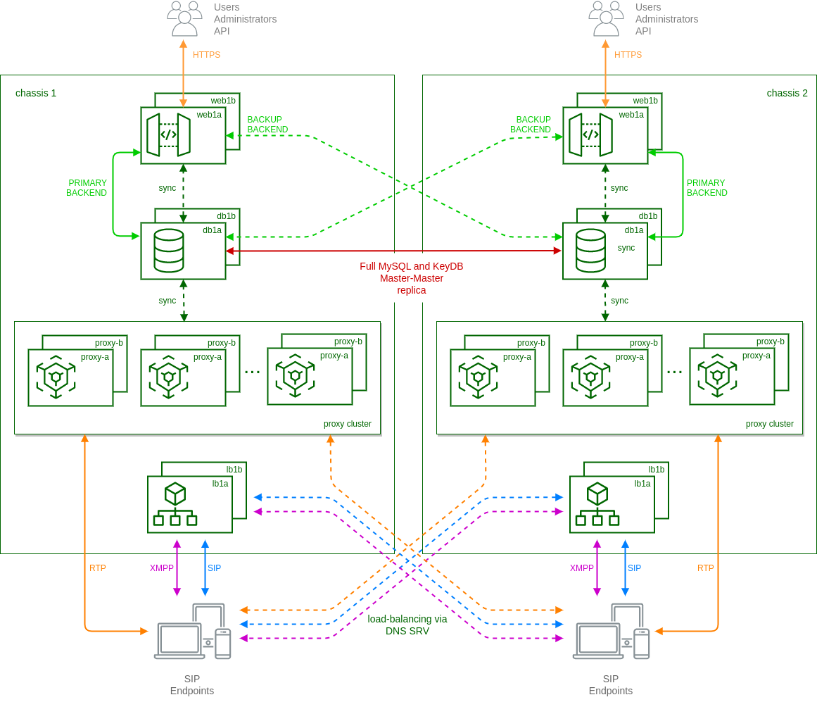
In particular:
-
each 'web' node has a built-in mechanism based on ha-proxy to select which 'db' node to use as backend. By default they always try to use the local node as primary connection and switch to the remote node in case of missing local connection or faulty local replica status.
-
mysql and keydb databases running on 'db' nodes are in a full master-master replica setup. This is to ensure the presence of same data (provisioning, locations, CDRs, etc.) on both clusters.
-
each cluster uses local 'lb' and 'prx' nodes as in standard carrier architecture, except when the called subscriber is registered on the other cluster. In these cases local 'prx' node can directly contact the remote 'lb' to route the calls to the final destination.
-
using DNS-SRV records, endpoints are usually registered on the nearest cluster. In case of failure of the local connection, then DNS-SRV is responsible to route new registrations to remote cluster.
-
ngcpcfg framework enables the operator to manage the whole system from one cluster node.
For any additional details on the Geo-Redundant setup and how to configure it, please contact Sipwise sales.
Instances
The Sipwise C5 instance is the basic building block to operate Sipwise C5 in a new way (using active-active concepts).
In summary, it is kind of the micro-services architecture for Sipwise C5. The main idea is to isolate each Sipwise C5 service, assign a dedicated floating IP address to it and allow it to work on a specific node/location.
An instance is defined as <service>:<label>@<location>.
| Term | Scope | Description |
|---|---|---|
<service> |
Mandatory |
NGCP/systemd service from /etc/ngcp-service/nsservices.yml. |
<label> |
Mandatory |
defines an instance, hardcoded at the moment |
<location> |
Mandatory |
Target node/type/cluster_set to start a service. |
The migration to the instances concept is in a stage of active improvement, however starting with mr10.5.1, it is already possible to active it and get its benefits. At the moment only the following services support creation of instances:
| Service name | Label name | Status |
|---|---|---|
kamailio-lb |
lb |
full support |
kamailio-proxy |
proxy |
full support |
sems-b2b |
b2b |
full support |
asterisk |
voicemail |
with small limitations: reminder service is not working, fax service is not working |
ngcp-rtpengine-daemon |
rtp |
full support |
There is no real limit to the number of instances which can be created for each service type (lb, proxy, sems-b2b etc.). Generally, a limitation is an amount of resources on the OS used for deployment.
In order to configure and enable instances on the Sipwise C5, please read this chapter: Instances configuration.
Active/Active and Active/Stand-by
Main difference between approaches
The main difference lays in the scope of the high-availability and the redundancy level, which can be provided by both of the clustering approaches.
It’s important to mention that Sipwise C5 by default (and in most cases) uses two sided clustering, which means: there are two locations where services can be deployed. That’s why the Active/Stand-by and Active/Active clustering approaches perfectly fit onto that.
Of course, it is still possible to set up a cluster with instances on the Carrier grade system as well and this assumes that there can be more than two locations for each type of the service (LBs, PRXs, DBs etc.).
Active/Stand-by
The Active/Stand-by clustering approach has been settled in the VoIP/SIP area for quite a long time, as well as in other telephony related areas not particularly related to the SIP and H.323 protocols. This approach used to be a good fit for that period of time, when technologies, protocols and libraries involved in the implementation of different cluster methods weren’t that much developed, extended and well tested in production. And it still can be a good fit for certain setups of customers/companies.
The main idea of the Active/Stand-by approach is to provide to a telephony setup a sort of redundancy, when one active side goes down for any reason (IP network issues, hardware issues in a datacenter, processes go down on the active side for any reason etc.), and bring up all the same services, as well as a shared IP address on the Stand-by side, in order to provide telephony based services back as soon as possible after the failure on the previously active side (master).
Such an approach of course has a list of negative aspects, which make it less efficient in comparison to the Active/Active setups:
-
Resources consumption - stand-by side does consume resources, even though does not process any SIP calls
-
Split-brain - under certain circumstances there is the possibility to fall into the split-brain scenario
-
Failover detection time - the clustering tools/logic must be smart engough to detect as fast as possible the failure on any of the cluster layers (IP connectivity, services failure etc.)
-
Failover migration time - the failover process still takes certain time to bring all services up on the stand-by side, from hundreds of milliseconds up to 5-10 seconds (and sometimes even more)
-
Services flapping - such setup can in certain cases create a 'flapping' case, when the Active side migrates back and forth, because the usual Master for any reason appears/disappears frequently
However, it has of course a list of advantages:
-
No load-balancing superstructure - there is no need to solve an obstacle with the load-balancing as a superstructure, because there is only one point obtaining IP traffic
-
Simpler debugging - this solution is much simpler to debug
-
Less complicated database clustering - no need to solve SQL/No-SQL replication obstacles, such as one when two sides perform write operations simultaneously (Master/Master replication)
Active/Active
The Active/Active clustering approach is already something not really new, and has been present for a while on the IP telephony market.
There are a number of important advantages given by the Active/Active approach:
-
Processing efficiency - doubled processing capabilites, when both sides of the cluster are engaged into calls processing
-
Better failover - in case of the failover, only half of subscribers/calls currently being processed need to be migrated.
-
Advanced maintenance - there is the possibility to switch the load-balancing to one side of the Active/Active cluster and to do a maintenance on the other, without an interruption of services
A list of disadvantages:
-
Load-balancing - there is a need to decide how the IP traffic (SIP calls) will be balanced between two Active sides, which can be based on different approaches (DNS SRV/NAPTR, transport based balancing, a separate load-balancing component)
-
Debug - the debugging of this setup is a bit more complicated. The Active/Active approach with instances has more things to configure, control and to maintain.
-
Database clustering - the Active/Active approach has a Master/Master database replication for both SQL and NoSQL, which makes the support of the database backend a bit more complicated as well.
However, even though the Active/Active approach looks much better in comparison to the Active/Stand-by one, it still shares a list of inherent difficulties with it:
-
Split-brain - in case both of the sites decide that the remote site is down, they both will undertake failover on themselves and hence there will be Active/Active x 2 setup, which will heavily affect systems in production.
-
Failover detection time - in the same way as with Active/Stand-by, clustering tools must be very accurate and quick to migrate services quickly in case of failure on one of the sites
-
Failover migration time - in the same way as with Active/Stand-by, failover takes time to migrate that half of subscribers/calls being affected at the moment
| it’s important to understand that in the scope of Sipwise C5 the LB component is an inseparable internal component facing IP traffic, and as such Sipwise C5 cannot function without it, because it is not a general load-balancing solution which works separately in front of the Active/Active service to balance traffic between two active sites. |
Active/Active approach implementation in Sipwise C5
There is a list of requirements which are to be fulfilled to deploy the Active/Active approach:
-
there must be a stable IP interconnection between sites
-
there must be a sufficient number of public/private IP addresses reserved, see information below
-
additionally, it is recommended to have a load-balancing solution present in front of two active sites, which will dispatch IP traffic
A list of the IP addresses needed in order to deploy Active/Active based on a PRO system:
-
x2 public IP addresses for cluster management purposes (optional)
-
x2 public IP addresses for LB floating IPs, external traffic
-
x2 private IP addresses for LB floating IPs, internal system traffic
-
x2 private IP addresses for Proxy floating IPs, internal system traffic
-
x2 private IP addresses for Sems-b2b floating IPs, internal system traffic
-
x2 private IP addresses to bind non-instantiated default services, such as database, ngcp-panel and other (optional)
| 127.0.0.0/8 cannot be used to bind instances on. |
| The IP configuration will differ on Carrier grade setups, for details please get in contact with the Sipwise Operations team. |
As already mentioned, each of the services will have to take a default location it prefers. Under normal network conditions, when there are no issues, services will be settled on their locations and interact with each other in the manner defined by the instances connections.
It is however recommended that services which must constantly work with each other are colocated. For example in the PRO setup: instances LB-1, Proxy-1 and SEMS-1 should be configured to run on location 1 by default, and instances LB-2, Proxy-2 and SEMS-2 to run on location 2.
| Each type of service requires a specific kind of connection to the SQL/NoSQL backend: Instances Connections to Databases |
The main clustering tools used in Sipwise C5 are:
-
Corosync - a transport mechanism for the cluster, which builds up an interconnection between all the cluster nodes, and ensures to carry the cluster data securely (encrypted)
-
Pacemaker - the brain, logic of the cluster. It provides all the algorithms and controls the instances via the systemd supervisor.
-
Custom developed part - there is a list of things which were internally developed, to improve the clustering capabilities and implement the instances concept
There is no need to debug/configure Pacemaker/Corosync separately, because it is maintained by the network.yml 'instances' section. So everything what is to be implemented in the Active/Active cluster must be configured in the network.yml 'instances' section, and any direct interaction with pacemaker, for example via crms or its configurations, can damage or negatively affect the cluster.
| If there are doubts about how to properly deploy the Active/Active approach over the currently existing setup, in other words to upgrade the system from Active/Stand-by to Active/Active approach, please contact the Sipwise Operations team to get assistance. |
Switch off normal services
By default instances are running concurrently with the standard services/daemons.
Such an approach has an advantage, it makes it possible for a system administrator to perform a smooth migration to the instances architecture. Also it’s worth mentioning that a migration to instances for all default services is not mandatory. It is possible, for example, to migrate only the kamailio-lb service, while all the rest of services can be kept running in a standard manner.
When the most important/required steps of the configuration are done and all those migrated standard services are not doing any significant work, they can be safely disabled, for that see Disable default services.
Limitations
The instances concept is still partially experimental and it will be improved version by version.
As mentioned before, some features might not be supported 100% for services migrated to instances (i.e. 'reminder' or 'faxserver' for asterisk).
An additional upgrade might be required in the future for those systems that have been migrated to the instances architecture, since it is still under a stage of improvement.
Example
Please check Instance Appendix for a full example of the 'network.yml' file of a PRO system with instances defined.